Tuesday, December 7, 2010

I'm making a note here.

Huge success.
After months of mostly ignoring my little CupCakeStrap, and tending to things in my life like gainful employment, education and whatnot, and I've restored the printing ability to the bot!

Many things have been changed, but the important ones are all I will recount for now. I've swapped out my never-really-worked mk4.5 extruder for Makergear's terrific Stepper Extruder, and suddenly everything "just works." I can dial in the worst settings ever, and as long as the temperature is about right, it prints. The clear PLA I got is no longer sitting unused, instead I have printed a good ounce of it into testing cubes, ipad stands, reprap power rings, and assorted do-dads. Now I'm focusing on tuning the profile, based on help over on #makergear and #reprap. Pictures to be posted soon.

Saturday, July 10, 2010

Success, Failure, Rinse, Repeat.


The controller bug has been conquered, by way of modified and recompiled firmware. A new extruder thermistor pin and a new thermistor table were all that I needed to get it up and running, and installing the mac ports of the various tools took less than an hour of concentrated effort.
Before I fixed the software I borrowed a techzone Mendel electronics set to use in case my hardware was irreparable, in return for a checking over of all the solder connections, a good testing, and some printed mendel parts. The stepper boards and motherboard initialized, and tested correctly, though I did not do any heavy lifting on them. The extruder controller is a totally different story. I wired myself a simple adaptor to turn the cat5 cable my motherboard uses into just the two serial comms wires used by the reprap wiring. This seems to have worked fine, I am incredulous that there could be something dangerous in two serial lines at 5v. When I plugged it all together and flipped the switch, above the fan spin up noises there were two distinct "pop" sounds and one particularly painful sounding hiss. I cut th
e power, and saw what I believe was the magic smoke escaping something on the extruder controll
er. I have not yet found out what parts burned, but I cannot find any visual leads with my naked eye. I re-checked all my wires, and tested the power rails, and found no issues. The controller board's power LED lights, but nothing else seems to work. I suspect it t
o be dead.

After bearing this news to the owner of the boards and promises to help repair the damage -- whatever it turns out to be -- I turned my attention back to extruding w
ith my own hardware.
The same guy who lent me his boards also gave me a nozzle that he
had cut with machines available at the University of Washington. I was not expecting a success from the first try, but the part, a combination nozzle and heatercore, managed to work on the first try with PLA. My mind was blown. We got to extrude at 255PWM, resulting in 33mm/s from the nozzle for at least 5 meters of testing extrusion. However, reality restored the normal order, and the nozzle jammed as soon as I stopped the extrusion to prepare for a print. I suspect this is because the thermal gradient is so tremendously long, as the entire hot part is 1cm long, followed by 2-3 cm of blank heater barrel The thermistor is a 3mm one, and placed just before the barrel enters the insulator. I will shorten it somehow and try again later this week. If this design works out my project will have spawned what I think may be another unique upgrade.
In trying to unseat the jam we seem to have burned out the Kysan 1156006 gearmotor. I am not sure what happened, but it no longer runs, even from my bench power supply. I'm working to replace it now.
In older news, I laser cut our machine a very nice filament spool and box, based 99.9% on the makerbot MK1 Filament Spool. Wheras the makerbot version runs $100, mine cost me $2 in metal nuts and bolts, as the handsome plywood was cut from free scraps, and the plastic was donated. It works pretty great, though I had to make my own feed tube modifications to get PLA to bend nicely and draw without kinking up. I think ABS would be perfect, but PLA is my target material. I'll just laser cut myself another one later...


Sunday, June 20, 2010

Marathon Man

So, I fixed the temp sensor. Or really, I replaced it. With a simple firmware hack (and installing scons) I moved the probe reader to a separate board, which is a more reliable system anyway. It also means that coupled with the heated platform board, my extruder controller now has "ears." I like that.

Now, my project partner and I just graduated from high school, and there was a celebratory party yesterday. At 4pm we began trying to run the now functional printer. First, I managed to strip the filament, and then in removing it I tore the leads off the heatercore. That was dumb. However, we dipped into the club supplies and made another one, and soon had an entirely fresh hot-end. We figured that with a fresh nozzle and barrel we might as well try and make it print with the PLA we bought, right?

Fast forward to 7:30am on the next day. The short answer is no. After a pretty solid block of more than 12 hours, the machine is extruding, but not reliably. We're seeing overheating on the board, barrel jams, slipping idler wheels, the works. Temp sensor hardware works great though. I am not a big fan of PLA now, but I am thinking we can solve some of this with better understanding of using PLA and a stronger extruder. We are using the new MK-5 pulley from makerbot, and it's great on ABS. It's not really biting the PLA though.

I'm amazed I am still awake, but evidently this is good project for keeping myself conscious with.

Thursday, June 17, 2010

Beautiful Music

Well, the extruder controller bug has been narrowed down.
The issue only surfaces if the sensor is plugged in, when the control panel is opened.
I presume this is because it is crashing when reading the sensor, and when it's not attached the circuit is returning something reasonable.
I'll be borrowing another controller soon, and in the meanwhile this one will have to be fixed properly.

In the meantime, I've been playing a lot with mid2cnc, playing pretty much anything I can find in midi format on the steppers. Flight of the bumblebee is a terrific test of printer speed. I ahev built up a pretty large library of midi files and their corresponding gcode, depending on whatever legality issues there might be I'll upload them. Also, I am fairly confident that I am the first to play Touhou theme songs on a 3D printer, but if I am not please let me know.

I've got a video of the machine playing, but I forgot to change the camera out of mirror mode, so I have to flip it horizontally.

Friday, June 4, 2010

Mad Extruder

We got the entire machine up and running for about two days. After a perfectly ordinary print, powerdown and sleep cycle (my sleeping), the machine started reading the temperature sensor wrong.
Completely wrong. With no thermistor attached the machine reads assorted temperatures between 100 and 220, but not the expected 255. After I tested the pins with a voltmeter (sensor attached), the readings were correct... for a short period. After 1-2 seconds of reading correctly the "temperature" skyrocketed back to 2XX. The same results can be had with another thermistor, so it is definitely on the board. An interesting note was that when heated to around 200 degrees Celsius the board begins to read the temperature correctly, and is able to regulate it fine.
However, given the complete unreliability of such performance I deemed that unacceptable.
A little help on the IRC indicated that either the resistor (4.7kohm) or capacitor (10uF) was damaged. I have no way to know what damaged them, but evidently something is broken. I probed the resistor, and got the correct resistance, but I managed to damage it by trying to re-seat it on the pads -- knocking off the soldering pads on the component itself. As I do not have spares of the parts, I scrounged and found the needed bits on some assorted and functional boards in the scrap pile, and replaced the capacitor and the resistor.

The board runs the extruder test program fine, and takes reprogramming correctly. However, it no longer communicates with the mainboard. This could be the side effect of re-seating a number of the components, as I felt like some were not well seated. I have yet to test the pins on the chip used to communicate over the cat-5 cable.

The timing could not be worse, because our PLA is now just sitting there, waiting, begging to be used.

Tuesday, June 1, 2010

A month of updates?!?


It's been a month since this updated? When did THAT happen?We've spent many more hours configuring the machine, changing various bits of the hardware and software, and we finally have it printing very well. Skeinforge took a lot of work, but the 20-odd hours poured into debugging nearly all of the options available were spent well.
We also constructed our very own heated build plate! Three times! The first time it was not strong enough, with an 8-ohm wrap, the second was too strong with 4-ohms (and burned up!) and the third try is 6-ohms and performing GREAT with a blue painter's tape surface.
Our heated build plate is essentially just a twirl of nichrome wire taped to a brass plate, with a plywood base and acrylic mount, with ceramic "tape" insulation inside. The top of the plate hits a reliable 90-110ÂșC in around ten minutes, and the makerbot firmware supports the reprap temp sensor 2.0 attached to port A6. The whole thing is pretty awesome.
Here's a picture of that, without the tape on it.
Those bolts that stick out are a little irritating, and I am working to make them obsolete. We've only head-crashed into them once, but it was truly nerve-wracking.

On the subject of nerve-wracking, skeinforge on my partner's machine self-destructed, and we cannot seem to restore it. Basically, we were running the raftless version, and when updating to the newest standard version it overwrote all of the settings. Now the raftless version is completely broken. This means we have only one machine that can run skeinforge well, yet Replicator G chokes and freezes, pausing the motors or extruder (but never both!). The fix for this has so far been to clone the copy of replicator G and skeinforge between machines, but we have not finished that yet.

In other news, we're using the new MK-5 Drive wheel from makerbot, we totally impulse-bought two of them. They're amazing, and we get something around 25mm/s at maximum motor speed. The insulator is showing some over-pressure wear and tear, but we can reinforce it/replace damaged ones.

We've ordered some awesome PLA from ultimachine, and as soon as it's here (measured in hours!) we'll be printing the first successor machine, probably a standard reprap mendel. Unless of course we decide to aim cheaper.

I hope to post again before a month passes, but with how busy I have become with work on this machine and work in school I do not know when my next chance will be.

Monday, April 12, 2010

Much, much better week

First Off:
The machine runs!

This last week we ordered replacement parts for the driver boards and ordered new driver boards for redundancy. We built up a plastic extruder based on the Plastruder mk-4, with modifications to the "dino" support structure. We borrowed a heater system from the supplies built for TEClub, as it is not yet being used, and began to test it out. I made some more
modifications to various plastic components, and tuned the hardware until I could rely on good movement and solidity. We saved the burned up board -- on the same day new drivers arrived. I ran some tests and confirmed it working, but because we could not have three of the same driver I have retired them for now, but they will be back in service on the next 'bot.

We had some interesting setbacks!
First and foremost, we found that the 200W PSU is not able to drive both the heater and the steppers, and would power down when both
were used. This was "solved" with the addition of a second PSU to power the motors. The two PSUs share a ground, but are otherwise not attached in any way. This is a sub-optimal solution, because as we found out the stepper motors would continue if for some reason the heater and its PSU went down (probably a short or something). We may invest in a really good PSU later. For now, it works.
Another issue we discovered was that despite acting as a loopback, the hacked-together serial cable really just seems to have stopped working. I bit the bullet and bought one that was tested from the Metrix Create Space, best place ever for people working on interesting hardware to hang out. With the new, working cable, we programmed all the boards (on the first try, too!).

From there, with working heater, boards, and motors
, it was only a few hours of debugging and reprogramming (extruder board inexplicably decided not to drive motor one on its own pins) for the machine to actually begin to extrude hot plastic. Today, we made the first few prints in just an hour of tuning skeinforge. We first tried a teacup, but the Y-stage went bonkers and every layer was off by many millimeters. We fixed that, and went with an open rectangle, and this showed us that we needed to adjust the feed rate -- we get something higher than expected, about 35mm/second. When the rectangle worked well enough, we moved on to the terrific dodecahedron. After a few false starts and some strange power-downs, this shape printed out very cleanly.

I think it looks great. We made another one so that each of us user/developers could have one. I also took a video of the build, and intend to use it for my presentation. That's in one day, so I'll be working on that for a few hours.

Visit our reprap wiki page for more info!

Sunday, April 4, 2010

Two Steps Forward...

Some large number of steps back.

This week we got the mobo programmed!
The Tx and Rx lines on the serial cable I hacked together were reversed, whoops. With the motherboard programmed (extruder still playing hard-to-get) we actually got the machine sorta running.

Now, we also found a solution (or, as I explain later, not a solution) to the
regulator problem.
The problem is the lack of regulators. The solution was jumping the 5v ATX line to the 5v output on the regulator pad, thereby supplying the board with 5v from the PSU. In practice, this was 6.4v.

This solution worked fine, though we were not able to make the board that sparked work (probably dead now). With two SMD 2.3 boards and one SMD1.2, We got it to connect to Replicator G with about 12 hours worth of resetting, plugging in, resetting, etc. After an 11 minute "print" (no extruder), there was a smell like ozone in the room. I ignored it. On the next startup, the smell returned, stronger. Ten seconds into operation, there was some serious sparking, smoke, and fire from one of the stepper boards. Capacitor c-6 had blown up.


Ouch. The capacitor has rotated perpendicular to its original orientation, and there is a hole burned into the board blow it. I am not yet sure if the chip itself is dead. if it is, that leaves us with only one SMD 2.3 board that still works... not much of a machine. The SMD 1.2 is on loan, and not meant to be a permanent addition to our machine.

With one week before presentation, classes starting tomorrow, and very little money left with which to order parts, this development is pretty bad. I have ordered more capacitors, some real linear regulators, and some resistors that were near the blast that might need replacement. The chips themselves may need replacement too, but I want to diagnose what we have and not spend money we don't.

Here's a shot of the board with the capacitor removed.


On a non-reprap note, I also dropped my laptop on the serial cable's USB end, and tore out a USB port. No way do I have the money to replace that ><;. I've simple amputated it for now. That leaves me with only one USB port. This is not, as may be intuited, a good week of work.

Oh, and my dog died. No, seriously.

Sunday, March 28, 2010

Minor... Setbacks

In an overnight "let's get this thing done all in one go" event, my project parter and I spent six hours cursing over the Arduino software, my ineptitude at understanding instructions, and the cheapo $3 serial cable's complete and utter failure to do anything at all besides act as a loopback.

Burning the sketch with my USBtinyISP never worked, and the Arduino software spouted unfixable errors. This may be due to it being the mac port of version 18. I'll boot ubuntu and install everything there and see if I can make it work.

In exasperation, I thought that maybe, just maybe, plugging everything in and powering it on would make things work. Actually, powering the motherboard might have been good by itself, but we had a far more interesting experience from everything at once.
As the PSU spun up, the Y stepper driver began to fiz from the linear regulator, sparking like a... sparkler. Needless to say, something was wrong.

Now, I know for a fact that the regulators we used are not the ones the schematics called for, but those were on backorder and these were extremely similar. Maybe not enough.
I should really go and dig up the data sheets for them so anyone reading this can learn what to avoid improvising with.

I really hope the $5 stepper chip on the board is not dead.

Friday, March 26, 2010

Productive Day

Whoo hoo!
Some days are just so much better work working in.

Today I finished the X and Y pulleys (by fusing the layers) and made modifications to the Cupcake's X platform so that it would take an M8 bolt rather than M6 or whatever it was.
I also removed the slightly bent Z threaded rod and replaced it with a much nicer piece, and used the not so great one as material for making idler axles from.
Then I re-assembled the stages, and they look usable! I just need to get the electronics working now, and I can begin to test out the machine's movement.

As for extruders, well, that's for later.
I have one extruder that we think will work, borrowed from the club.

No pictures today, as the camera was borrowed for something else.

Tuesday, March 23, 2010

Week's Worth of Update


I think I said I was going to update "tomorrow" two weeks ago.
Whoops.
Time sure passes fast when you're having fun!
Anyway, a LOT of stuff has happened, which I'll have to recount concisely.


First off, I decided that the mild warping on the plywood Z platform was not going to work. That was a really easy fix, as I just had to go find a sheet of acrylic of the right general shape, saw it squared, and lazzor away.

The same day, I got tired of the Z-stage coming off of the washers that are used to move it around.
At the risk of cracking it, I designed and installed some extra layers to hold it in place. I'm quite happy with how they turned out, actually. The result is that the platform cannot come off of the washers, they are totally locked in place. This has added some resistance, and it seems to stem from a moderately bent Z rod. I have some more M8 left over, so I think I'll replace it.

The other thing from last week wa
s producing the X and Y motor pulleys... yet again based on random belts I pulled from printers. Th
ese were a bit larger than I expected, but Griffin was able to produce the correctly toothed pulleys for them with only one re-try. He would model the pulley and send me the file, and I'd run to the laser and cut it out, then bike over to his house to see if it worked. I think the plan worked great. They pulleys are pretty much perfect, and base
d on a comment on my last post I've opted to reverse my layer order so that the edges of the pulley are convex. This means the belt will be held tighter in the middle and due to variations in radius resulting in different RPM at the edges, it ought to stay on better too.


I've been reminded by two people now to talk about one of my improvisations on the machine.
Because I could not find a source for linear bearings that were both low friction AND cheap, I decided to scrap the designs that need "precision steel rod" and substitute my own low-cost alternative. In this case, I went to a local and small hardware store and poked things together. I found a meter of aluminum rod for less than $5 and a
foot of good copper tube for about $4. I was in luck, not only d
o these two things have a low coefficient of friction, they were cheap! I bought them and then sawed the rod in half and the tube into short sections the same length as the X and Y stages are wide. Now, the tube's outer diameter is not the same as the inside diameter that the makerbot was made to take... so I lazzored out an entirely new XY stage. The rod is M8, so it fit correctly. However, I made a silly error and made my cut exactly 1cm off from center, so one rod was too long and the other too short. As a result I had one rod that simply needed trimming to fit, and one that could never be augmented.
Quite the dilemma, or so I thought. Then I remembered that I have a laser cutter at hand. I simply made some hole-extenders from the endcap design and bolted them onto the inside. Turns out there is a lot of wasted space in the Makerbot Cupcake. Another triumph of frugality and improvised parts!

Next up, I finally discovered why my package from Digikey was taking so long... I had supplied the wrong address! The keys 9 and 6 are hard to accidentally interchange, but what can I say? I re-ordered and the package arrived last monday (yesterday as of writing). I gathered up everything I thought we would need and carried it all over to Griffin's to solder the last parts onto the boards. Great success! They're looking nice, and the only thing that has an issue is the big resistor on the motherboard. It's there to put a load on the PSU to get it to turn on (talk about an odd safety system). Sadly, we got a 5W .30ohm resistor... the machine needs a 5W 30ohm one. Whoops. We also have a 5W 3.0ohm resistor, so thi
s is comical. If only we could test it.

That brings me to the next item I want to talk about! I read this walkthrough on converting a nokia phone cable to a USB->TTL serial cable, and decided that that was the most cost effective way of getting the needed programming cable. I was able to get one of these cables for $3, shipped. That's a terrific deal. Or it would be, if I could make it work.
The cable declares itself to my computer, and USB probing makes me think that it is indeed working. However, in the step where I must probe the voltage on the Tx and Rx lines, I get a minute amount of power out of it. Not sure how to continue, so I just soldered the lines to a makeshift port anyway, though I am afraid to try to use it. Would rather not have to buy one.
If anyone knows what my issue there might be, let me know or I just might fry something.

Tomorrow I'll be building an extruder based on the PAXtruder, but with a NEMA-23 stepper as a drive. Ought to work, but I have not done any math to prove it. I'll also be making four more conventional gearmotor extruders, for the TEClub to use with our always-advancing Prolight Mill headcrab. It may be able to print up to six copies of something at the same time!
Lots to do, lots to do!

Sheesh, this is a very long post.
Thanks for reading!

Tuesday, March 9, 2010

Makeshift Motor Pulley


So, I had time to work out another solution to my lack of a motor pulley.
I decided to build it around a rubber wheel-thing from a paper roller out of a printer that gave up its belts for the machine anyway. This means I no longer have to worry about much in the way of play on the attachment between pulley and motor.
It works pretty well, but I made an error when fusing the layers, and the two layers that constitute the toothed section are not aligned correctly, and the belt skips every 20 turns or so. I've managed to run the motor with an older reprap stepper driver (powered from a SCSI enclosure) and it works great, minus the skipping. The driver produced so much heat that I was afraid to burn it out by running for too long. The enclosure PSU is probably made for more demanding devices - its normal function is as a soldering station power supply with a few PC fans attached in series around the edge to suck away fumes.

I'll make another one tomorrow, and clamp it to dry with the belt attached.

Monday, March 8, 2010

Custom Laser Cut Pulleys


As I mentioned before, my project partner and I decided to re-use the belts from an assortment of printers and scanners, which meant we needed to design pulleys to go with them.
Yet again, the laser cutter proved invaluable, allowing us to try design after design until we no had perfect meshing. Griffin did the measuring and modeling with calipers and Inkscape, I worked the laser and assembled the four layers needed to create a pulley from a flat sheet. We used an acrylic solvent glue, and they're now single solid objects. They fit the M8 rod perfectly, and are then clamped down with nuts and washers.

The motor-fitted pulley still has some issues however, as neither of the versions we have tried are quite right. Luckily, we have tons of plastic to work with, so the limiting factor is (as usual) time. I hope to report back with success tomorrow.

If I ever figure out what model printer the belts came out of, I'll upload the designs to thingiverse.

Documentation


Well, I was immediately reminded that I should post some visual media about these projects.
Here goes.
Firstly, here is the initial photo I took of the Cupcake, after I laser cut the plywood body. Note the acrylic side; I initially wanted a machine that was entirely clear, but I forgot to compensate in the designs for a 1mm greater thinkness, and thus all the tabs failed. This was taken in October, only weeks into the project.


Next up is the laser-cut X and Y stages, they're looking nice and clean, and are the correct thicknesses. This was completed less than three weeks later, possibly faster even. I plan to illuminate the build platform sometime in the future, I'm sure it will look terrific.

After that I lazed off and took no more pictures until just recently, when I worked out the improvised X-Y sliders. The final picture is the most close to current version, you can see the rods and tube in place, as well as the mostly-done electronics clingning to the side half heartedly. None of them are testably complete, though I have burned the bootloader for the extruder controller (ironic, as I do not even have one yet!).

Sunday, March 7, 2010

Real Content!

Ok, might as well use a blog I already started to talk about stuff!

As a re-introduction, my name is Ben and I'm a student at Roosevelt High School. Here, like many places, seniors are tasked with completing a self-guided project (a "Senior Project," so creative a name).
My project was, originally, running my bike on an electric motor. I got bored with that idea, and decided to build an air engine, the sort of which you might have once seen on a powered airplane model. I acquired plans for a five-piston engine, and began to build it, but got distracted and bored yet again. Finally, I settled on something, and that's what this blog is now about.

A friend of mine from middle school became obsessed (to put it lightly) with replicating machines. He introduced me to the RepRap project some time in sophomore year, or something like that. Possibly earlier. In junior year, and he brought up the subject again.
I realized that Roosevelt High School was already positioned perfectly for launching into reprap production, and even had a laser engraver capable of cutting sheets of acrylic (sourced as FREE scraps from ever-awesome local businesses). Researching the topic is relatively easy, and there's a big community already in place (and growing) to look for news from.

Boom, RHS' TEClub* was born. We're a collection of students with varied interests in technology. At the moment we're working with a local rep-strapper to convert our ProLight CNC mill into a three-six headed FDM beast. That was a bit more than a year ago now, and we've made serious progress (hindered by student laziness). We've got our machine "nearly working," which means... we need to build extruders, fix the firmware, and probably some other things that should have happened a year ago. We're also making a laser-based 3D scanner (someday we'll have software), and some other things.

Whoops, this post was about me, more on TEC later.

Anyway, after a half-year of TEC and one scrapped laser-cut Darwin, I realized I was now a senior. Time to kick it up a notch perhaps. As I stated earlier, my senior project ideas were pretty crazy. With help from best friend Griffin (original introducer), I decided to aim even higher and build my own 3D Printer. The darwin parts were done, but the price on the non-lasercut parts was too high. That's when I found the 
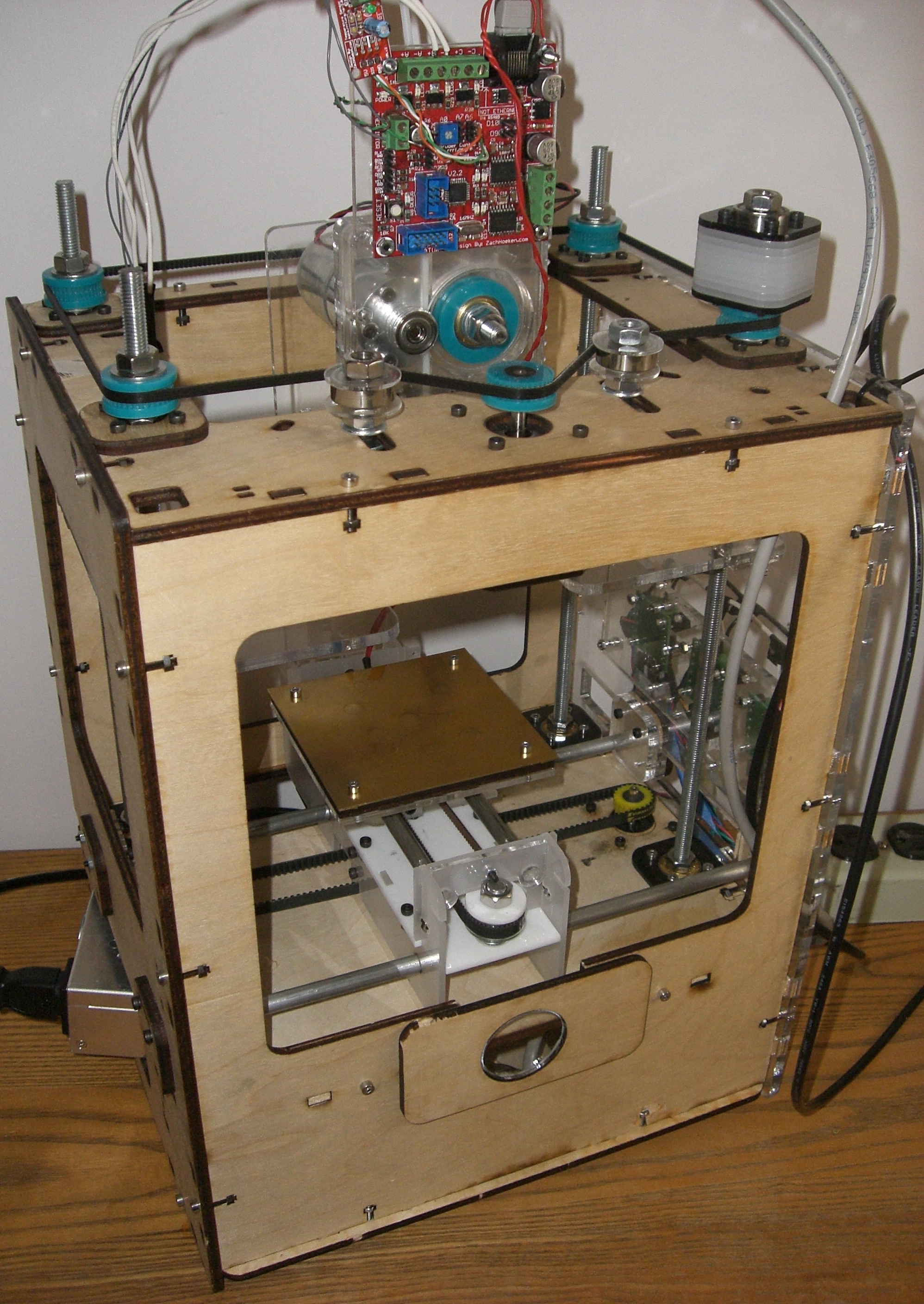
Makerbot Cupcake CNC. A simple printer, less print area than the Darwin or later Mendel, and a huge price tag. However, I realized that I could probably get all the parts locally, and a large part for free.

The plywood was mooched out of TEC's supplies, and laser cut for free. That and the free acrylic provided me with 50% of the parts (by volume). As for the electronics, well, I knew how to solder, and so I simply ordered the PCBs alone and over time ordered the components from Mouser and Digikey (a note about this later!). As for the other parts, well, I have Tacoma Screw nearby to go to for cheapish nuts n' bolts, and Harwicks' for other parts.
After thinking about it, I decided to improvise wherever a component would cost too much(more than $50, I'm cheap), and so I have a custom $10 X-Y stage from aluminum rod and brass tubing, and I've been designing a laser cutting pulleys for belts taken from printers. Actually, it was Griffin that did the designing for the first pulleys on Z. They work great.

That note about the electronics? Yeah, never, ever order $40 in crucial parts via usps just because they are the cheapest! It's been three weeks, and they're still in the mail!

March 7th, and the electronics are nearly done (grr), the frame is complete, and the X, Y, and Z stages need little more than their pulleys to be cut out. The extruder is non-existant, and I need to build the entire thing - luckily, I have a laser cutter.

That's all I can write for today, but I'm going to go submit this to the aggregated reprap and makerbot blogs. G'night all.


* Depending on who you ask, this is either "Tacgnol" or "Torchwood" Engineering Club... Club.